A town-centre building with shops and a restaurant at street
level, converted into seventeen self-contained flats on the floors above,
with the commercial units kept in use. This is the set a contractor prices, a building
control officer checks, and the trades build from.
Sheets issued
37A1 landscape, A.01–A.37
New dwellings
17Lettered A to Q
Ground floor
KeptRetail and restaurant retained
Location
KentDrawings issued 2026
What a construction sheet actually is
Not just a drawing — a controlled document. Every sheet carries the same furniture: a
ruled border, a title block, a materials key running existing / demolition / new brick / new
stud / new roof, a drawn scale bar, and its number in one continuous series.
The set moves in three movements: survey what is there, set out
what replaces it, then specify every junction and system.
About these images
Every drawing below is from the real issued set. Anything identifying the building or the
people involved has been removed: the address and street name, the client and job number,
the site location and aerial sheets, and the names of neighbouring businesses. Personal
contact details have been stripped too. What remains is the drawing craft and the
construction content, which is what this is about.
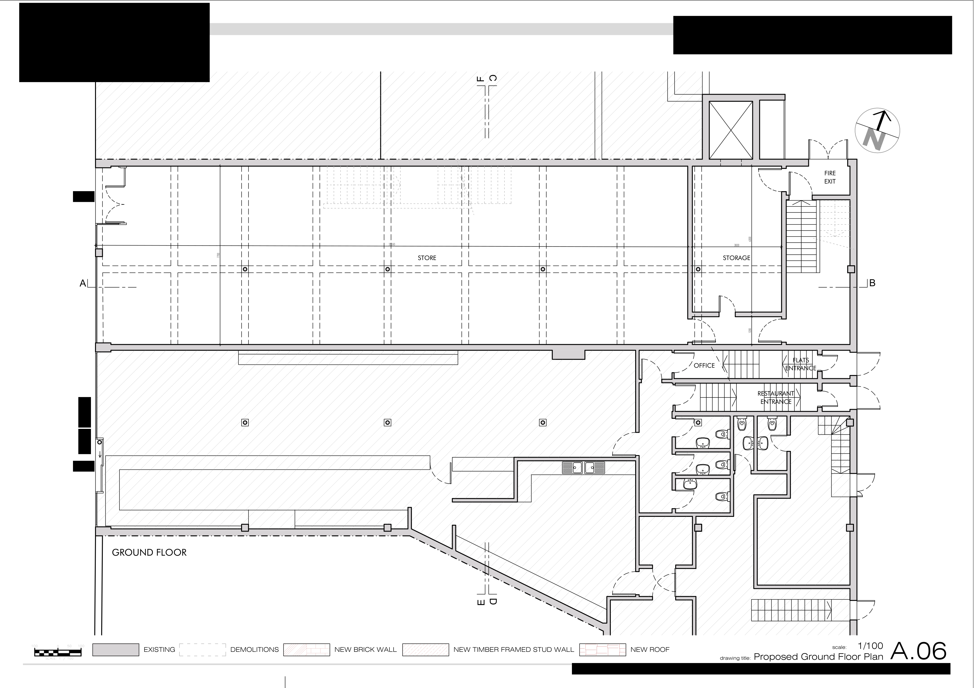
A.06A whole sheet, as issued. The format every one of the 37 sheets follows: the plan itself, the materials key, the drawn scale bar and the sheet reference. The blacked-out zones are the practice logo and contact block, the title block carrying address, client and job number, and the copyright line.
Before any drawing, the written spec
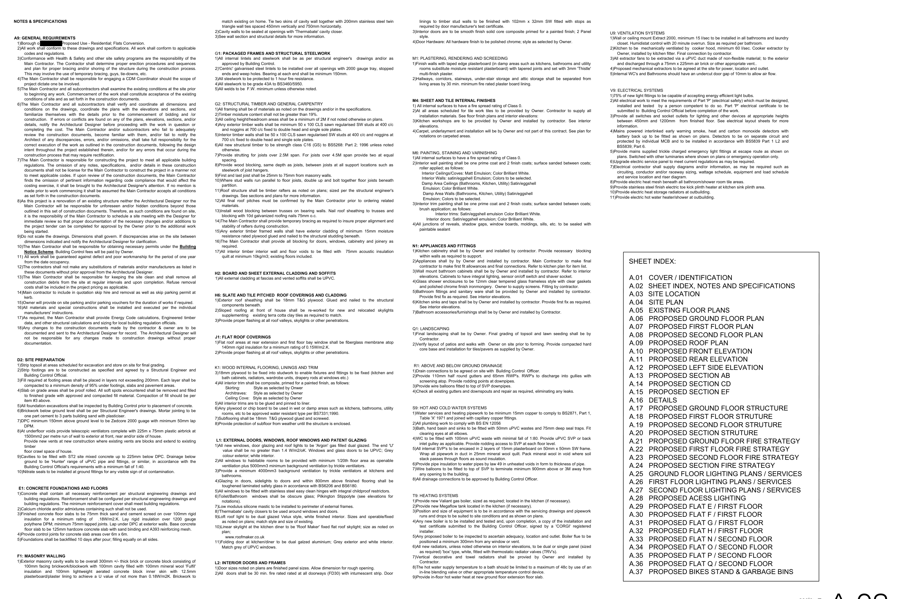
The set opens with a sheet index and a wall of specification organised by trade —
general requirements and site preparation through concrete, masonry, steel and carpentry,
roofing, glazing, plastering, finishes, drainage, heating, ventilation and electrics. These
clauses set the standards the drawings then apply: U-values, fire ratings, product
references, tolerances, and who supplies what.
A.02Sheet index, notes and specifications. The trade-by-trade written spec and the full drawing index on one sheet. One incidental reference to the local authority has been blanked.
You cannot convert a building you have not measured
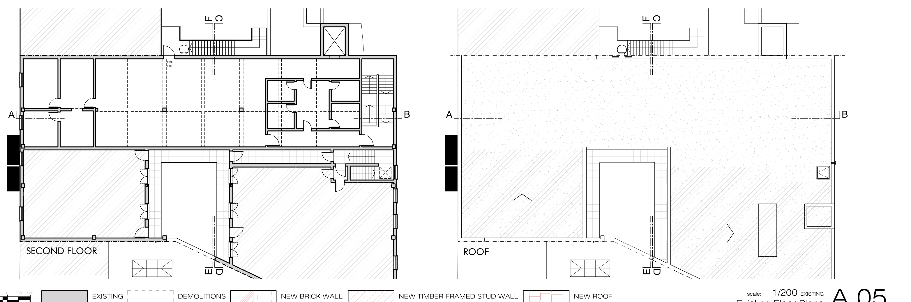
The set records the building as found, floor by floor and in section, so new work can be set
out against real dimensions and building control can see what is kept, altered or removed.
A.05Existing floor plans. Plain survey drawings of the building before conversion: upper floor and roof as found.
The proposed layout
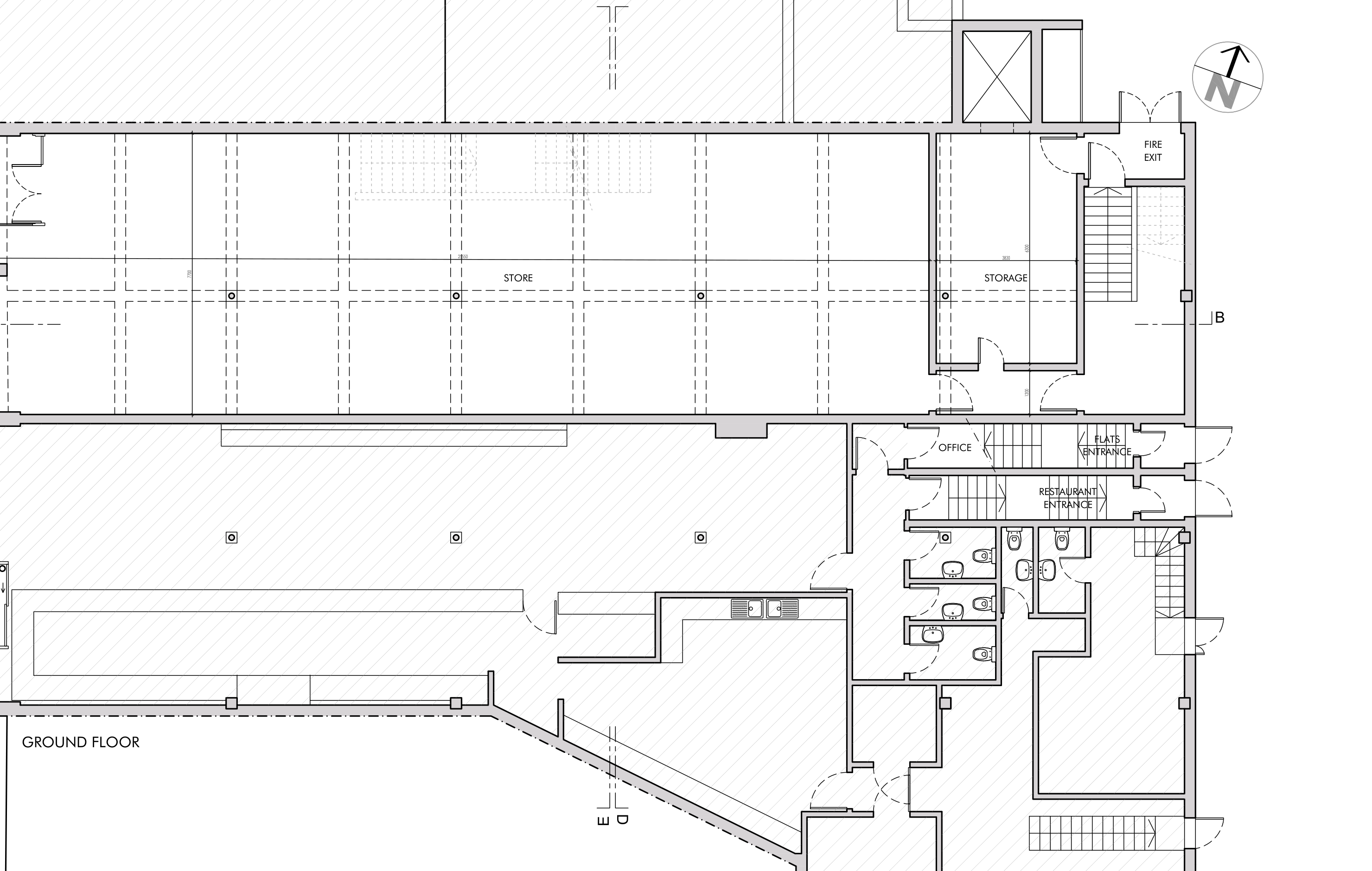
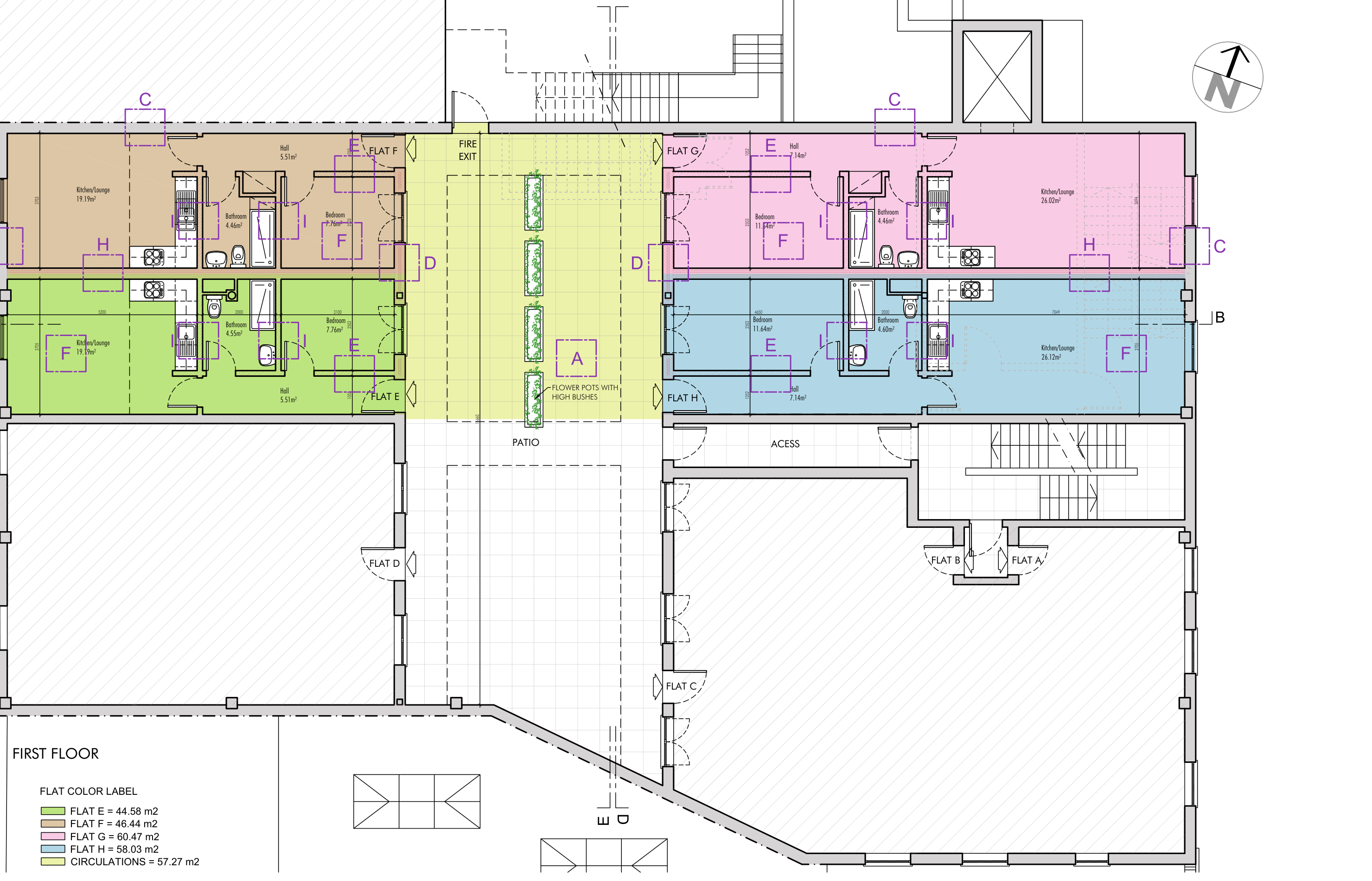
One level at a time. Walls are drawn in the key’s hatches, so it is immediately clear
what is existing fabric, what is demolished, and what is new brick or new timber stud. Flats
are colour-coded and scheduled with floor areas; rooms are labelled and sized.
A.06Proposed ground floor. Commercial units retained; new flats entrance, stair cores, stores and WCs inserted at the rear.
A.07Proposed first floor. Four flats around a shared patio and access route, with the area schedule bottom left.
Elevations and sections
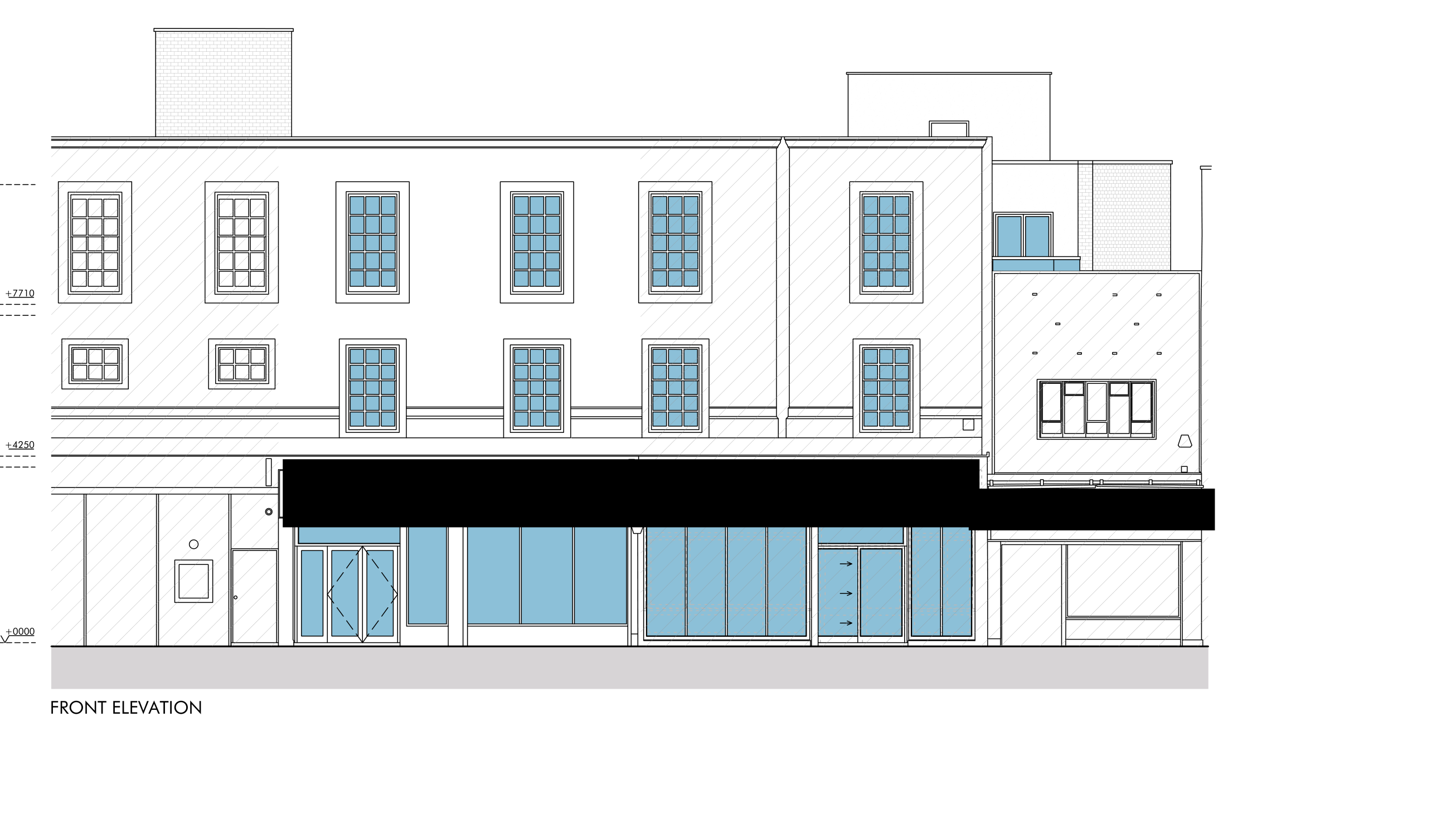
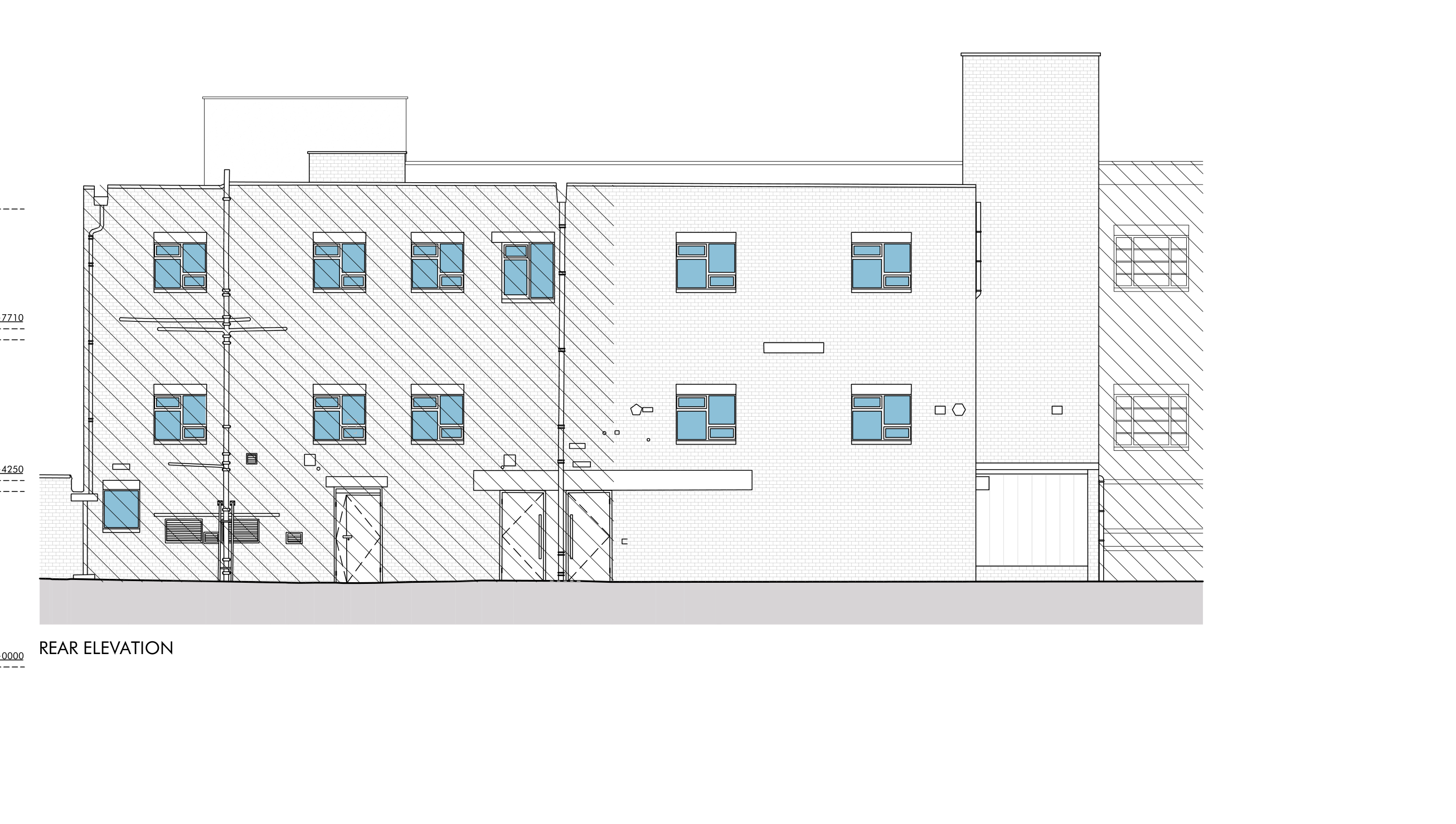
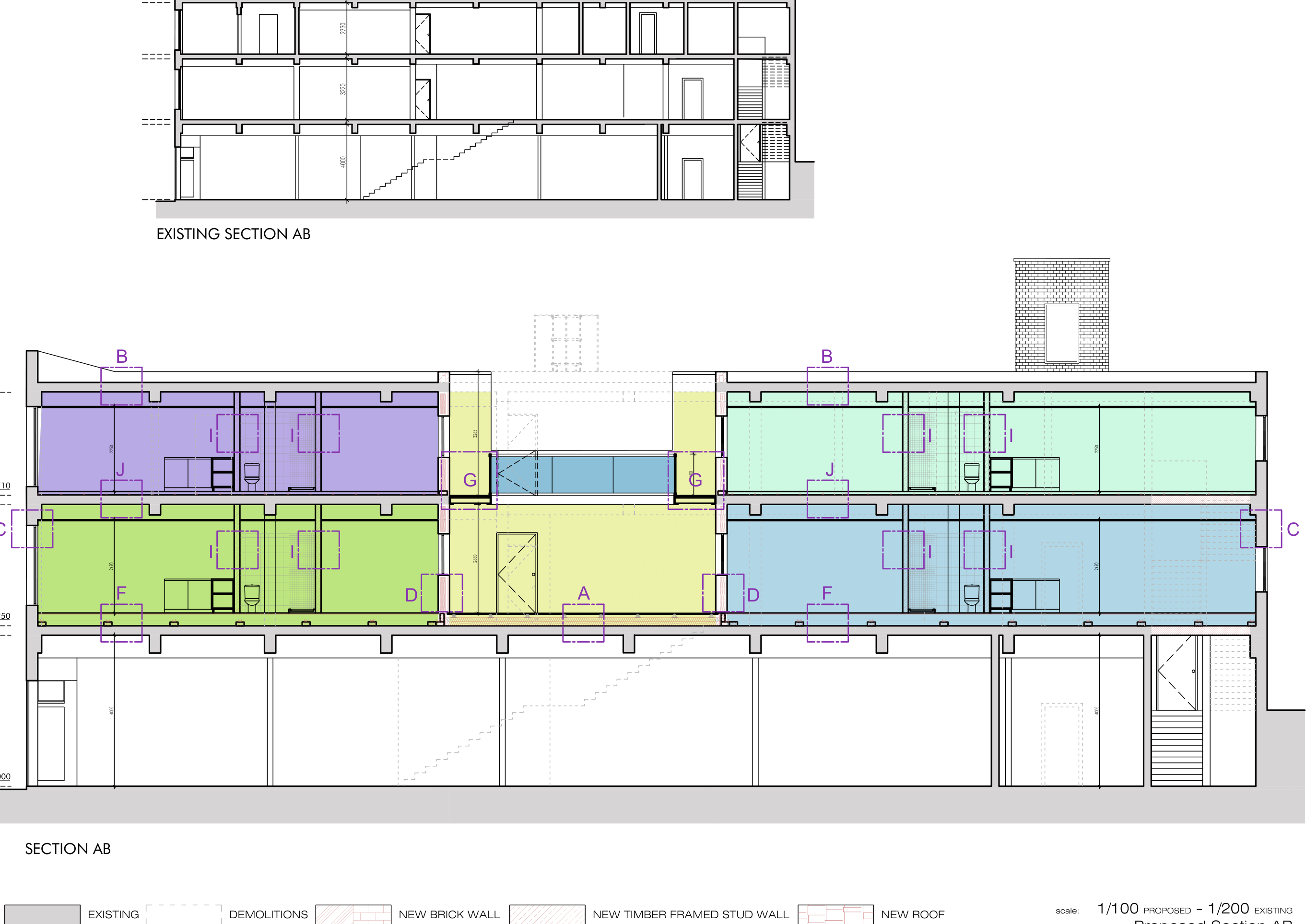
Elevations show the building’s faces, what changes and what is kept, with finished
floor levels marked. Sections cut through to show storey heights, the relationship between
old and new floors, and where each construction detail applies — the dashed key tags
point back to the detail sheet.
A.10Proposed front elevation. New windows to the upper floors above the retained shopfronts. The existing shop signage band has been redacted.
A.11Proposed rear elevation. The back of the building, with the new stair tower and rainwater goods.
A.13Proposed section AB. Existing section over the proposed section, flats colour-coded, storey heights dimensioned, detail keys A to J tagged where each build-up applies.
Where the set says how it is put together
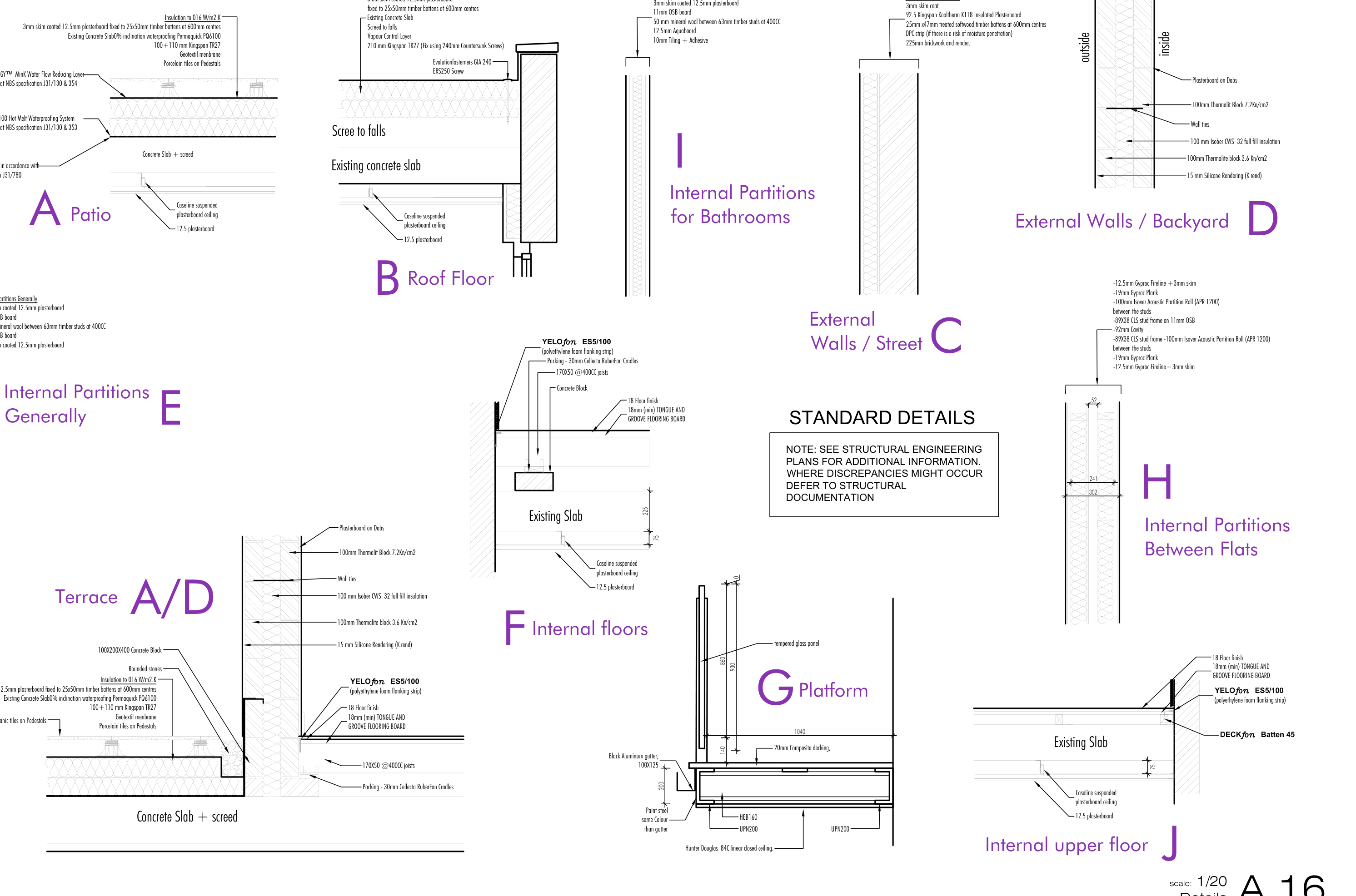
Every wall, floor, roof and terrace type is drawn at 1:20 as a labelled build-up: layer by
layer, product by product, with the target U-value noted. On site, the letters on this sheet
are what the plans and sections refer back to.
A.16Ten build-ups at 1:20. Patio, roof floor, external walls to street and backyard, internal partitions, internal floors, balcony platform, party walls between flats, bathroom walls and upper-floor terrace.
Structure, fire and services
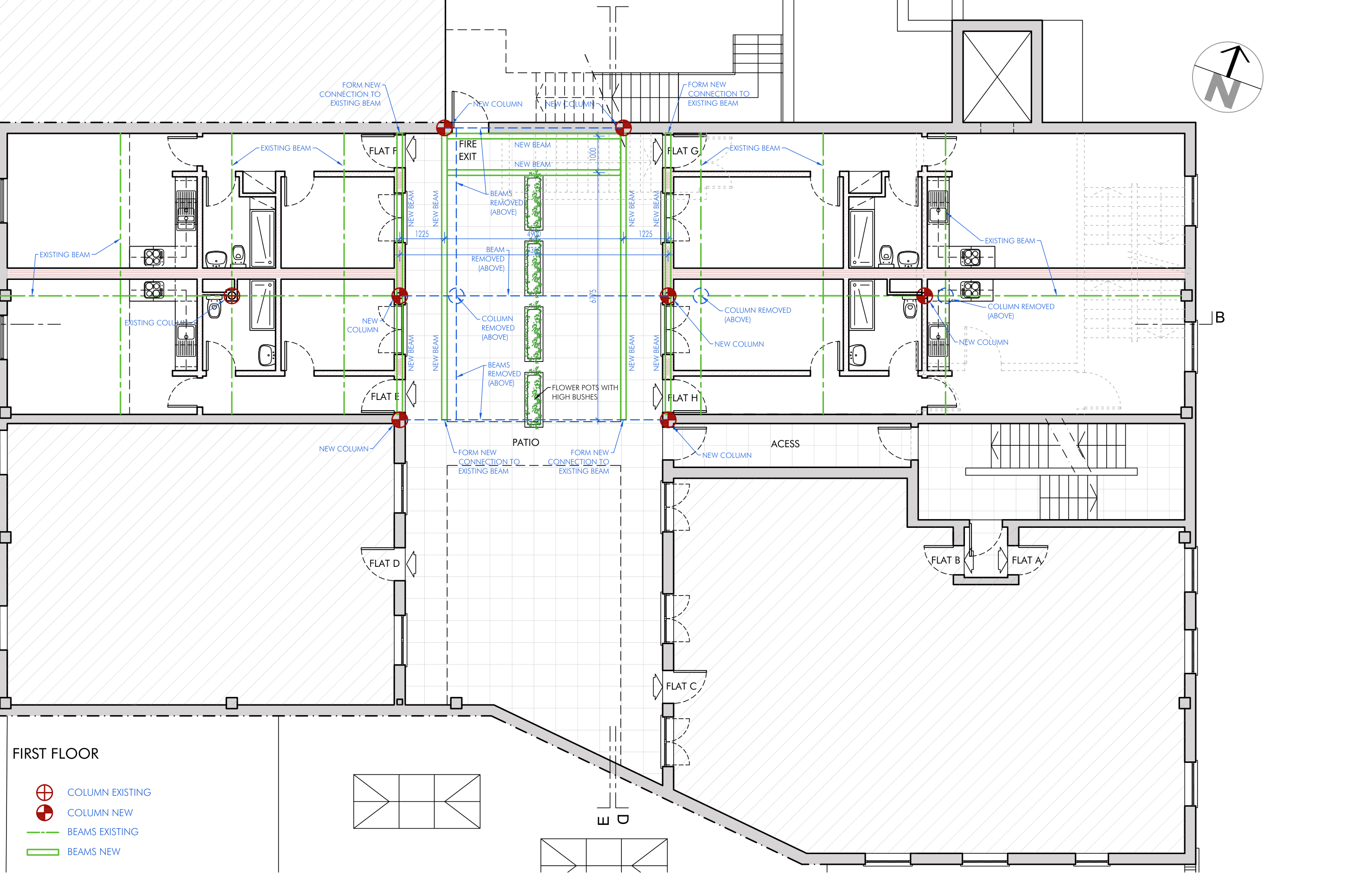
Three more layers run over the same plans. Structure marks which existing steel is kept,
which comes out once load is transferred, and where new columns and beams carry the new
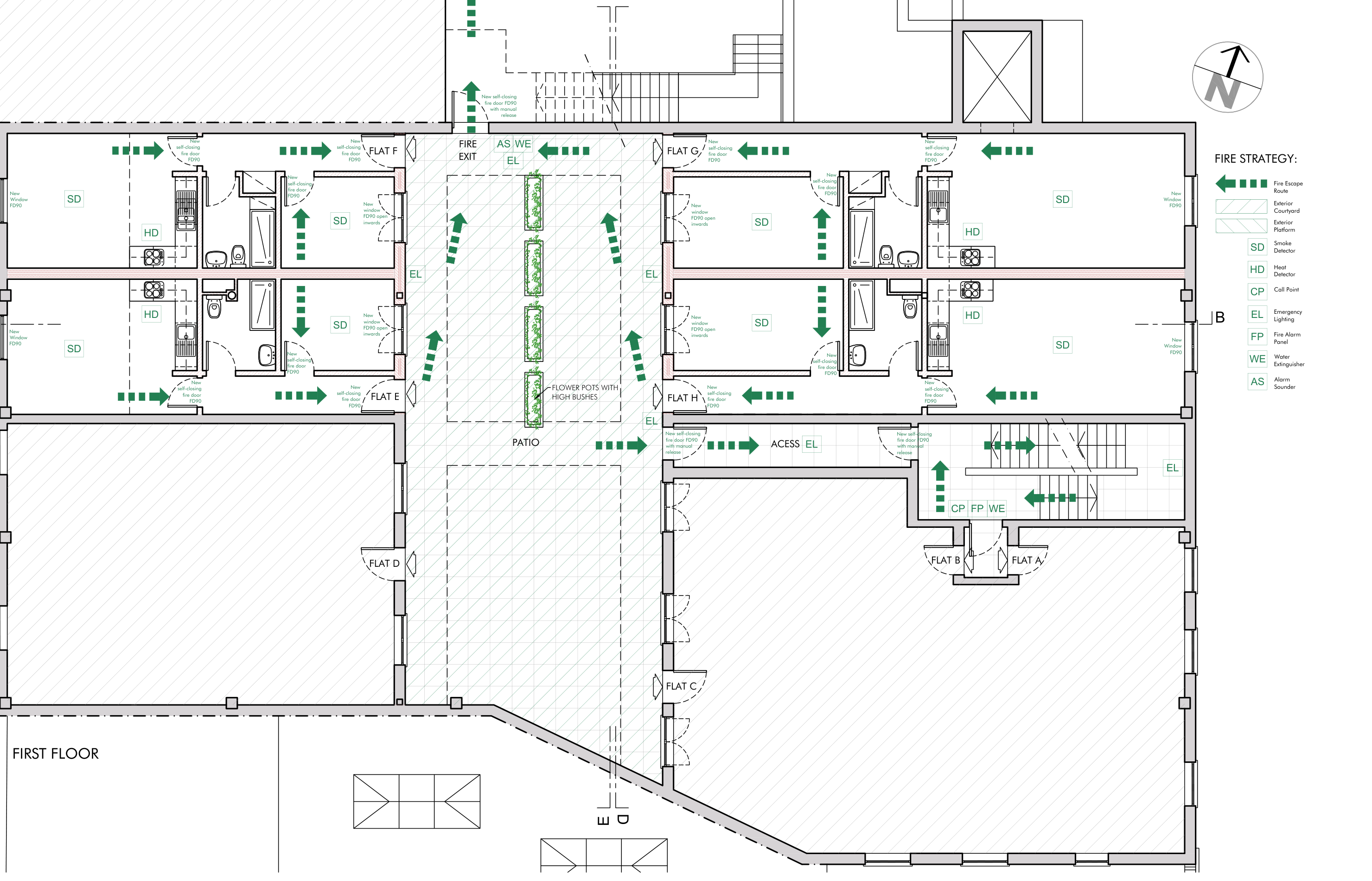
layouts — deferring to the structural engineer for sizing. Fire strategy tags every
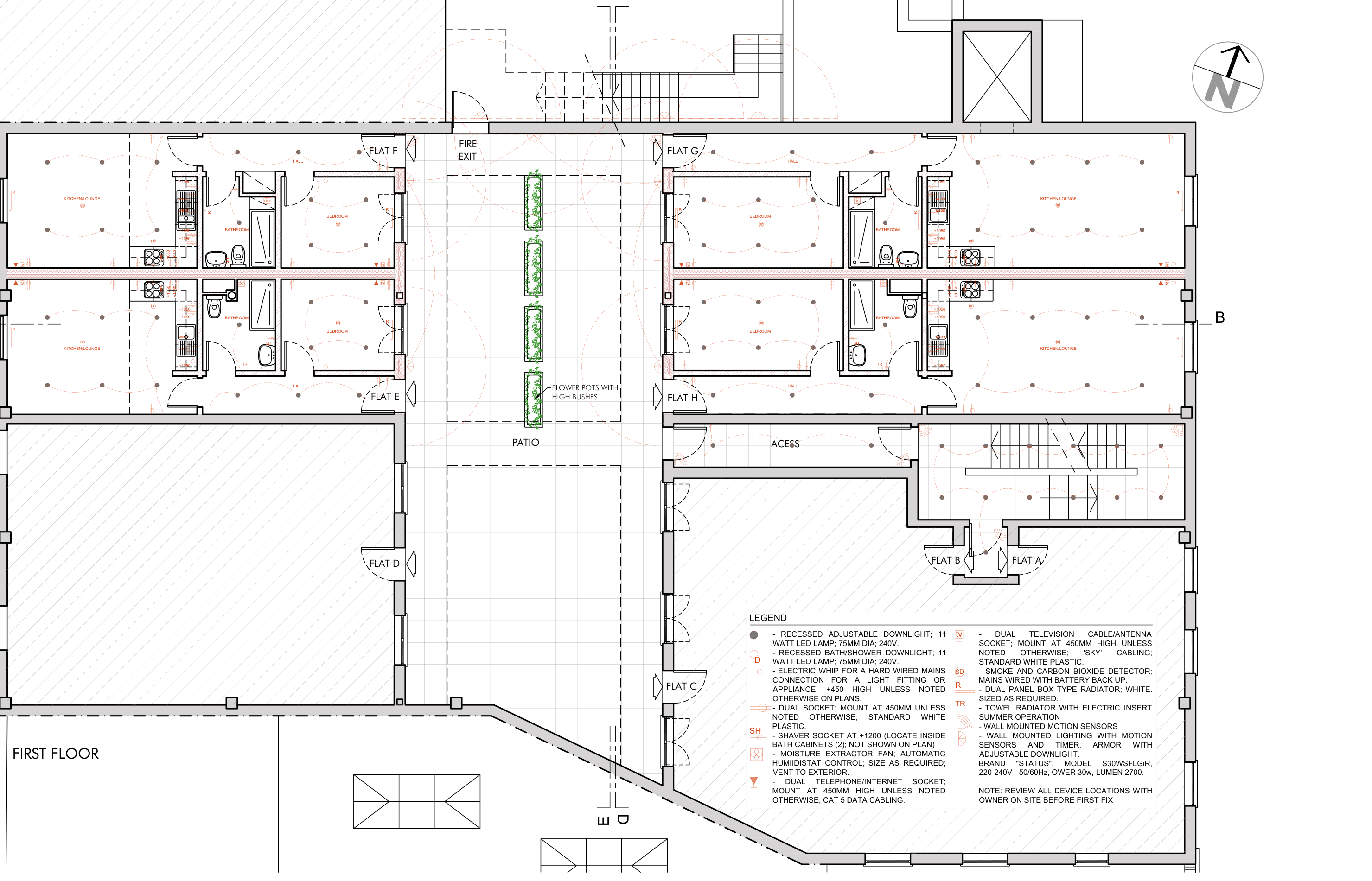
flat entrance and every window onto the escape route with its rating. Services place every
fitting, socket, switch, radiator and extract fan at a set mounting height.
A.18Proposed first floor structure. New beams and columns form the flats; some existing members are removed and new connections made to those that remain.
A.22Proposed first floor fire strategy. Every flat entrance and every window onto the escape route tagged with its fire rating.
A.26Proposed first floor lighting and services. Every flat laid out with lighting circuits, sockets at fixed heights, gas and water points.
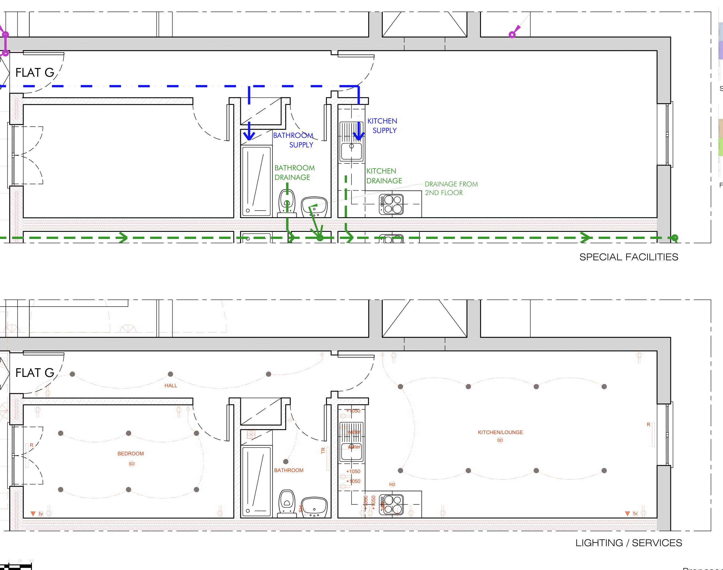
Then every flat gets its own pair
A special facilities plan tracing kitchen and bathroom hot and cold supplies and drainage
runs, including drops to and from the floor below, and a matching lighting and services plan.
This is what the plumber and the electrician work from, flat by flat.
A.31Proposed Flat G, first floor. Supply and drainage routing above, lighting and services below, for one flat — showing how service runs pick up drainage from the floor above.
And the small things at the end
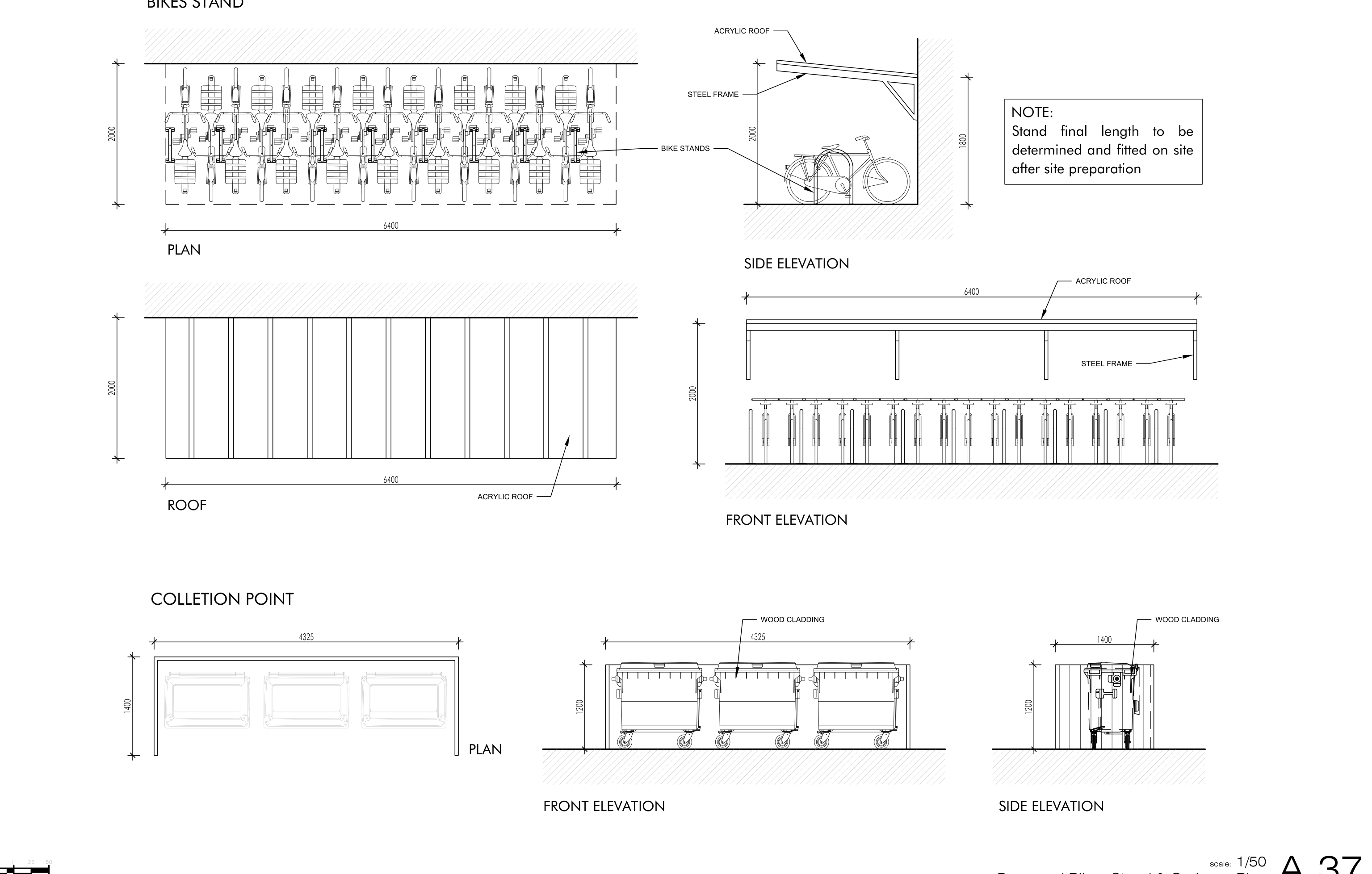
The set finishes with the external structures the conversion needs: a covered cycle stand in
steel with a translucent roof, its final length set on site, and a timber-clad refuse
enclosure sized for three communal bins.
A.37Bike stand and bin store. Plan, front and side elevations for both structures at 1:50. A steel-framed cycle stand with a translucent roof, and a timber-clad enclosure for three communal bins.
→ The construction approach, in brief
External walls
Street wall. Existing 225 mm brickwork lined internally with
92.5 mm insulated plasterboard on treated battens. U ≤ 0.2.
Backyard walls. Rendered cavity, dense aerated blockwork both leaves,
full-fill mineral wool, silicone through-render.
New cavity walls. 100 mm facing outer leaf, 100 mm full-fill
insulation, aerated block inner leaf. U ≤ 0.18.
Separating construction
Between flats. Two independent stud frames, fireline board plus dense
plank each face, 100 mm acoustic roll, clear cavity between frames.
Floors. T&G board on resilient cradle battens over 170×50
joists, acoustic quilt to all voids, suspended plasterboard ceiling, resilient flanking
strip at the perimeter.
Roof and terraces
Existing pitched roof reworked around new and relocated rooflights, clay tiles
matched.
Flat roofs: fibreglass membrane over 140 mm rigid insulation.
U ≤ 0.15.
Terraces: hot-melt waterproofing over ~210 mm rigid insulation, porcelain pavers
on adjustable pedestals.
Fire
FD90 self-closing fire doors to flat entrances and protected routes; fire-rated windows
opening inward onto the escape route.
Mains interlinked smoke, heat and CO detection with battery back-up; emergency lighting
to escape routes.
One square metre high-level openable smoke vent at the top of the stair.
Glazing
Argon-filled double glazing, U ≤ 1.4. Grey outside, white inside.
Obscure glass to bathrooms; toughened or laminated safety glass to doors and below
800 mm; trickle ventilation throughout.
Services and drainage
Recessed 11 W LED downlights; sockets at 450 mm; data and TV points.
Gas boiler and unvented cylinder where required; TRV panel radiators; electric
underfloor heating to bathroom tile areas.
Humidistat extract fans ducted outside from every bathroom and kitchen. Soil pipes
boxed in double plasterboard and wrapped.
What was redacted, and why
To keep this about the work rather than about a specific building or its owners, the
following were removed from every image: the property address, postcode, street name and
neighbouring house numbers; the client and project name and the job number; the site location
plan, ordnance survey extract and aerial photograph, which are not shown at all; the names of
neighbouring businesses on the front elevation; and the practice’s personal contact
details and office suite address.
Tell us what the building is and what you want it to become. You will get a straight view on the route, the drawings it needs, and what it takes to get there.